| LIBROW | ® |
| Products | Solutions | Vehicles | Articles | Inquiry | Contacts | My account |
Article 4
Pendulum in viscous media
Limited offer
Professional Librow Calculatorvisit
for free
- Bessel functions
- gamma function
- complex numbers
7.4 MB for Windows
 |
Download MatLab pendulum demo (zip, 2 kB) |

1. Introduction
The article was written as result of R&D for a project related to development of ultrasound probe positioning mechanism. The problem considered in this article can be outlined as follows: sonic transmitter moves along arc in viscous media with some predefined velocity and the task is to switch the motion direction in minimum time.
The demo package includes 2 files — MatLab script and description:
- pendulumdemo.m — MatLab script,
- readme.txt — description.
Some technical notes on demo:
- To run the sample MatLab should be installed on your computer.
- Unpack the sample and copy pendulumdemo.m file into MatLab work directory.
- Start up MatLab and type in:
>> pendulumdemo
2. Problem consideration
Mathematically the problem can be posed as follows.
The equation of transmitter motion can be written down in the form
| (1) |
where Ω is angular displacement and U is external torque. The equation is equivalent to the equation of pendulum in viscous liquid. External torque is limited by some value:
| (2) |
Our boundary conditions are:
 |
(3) |
Here time T is unknown and minimum. These boundary conditions say we should return in the same point with opposite velocity. So our task is to find function U(t) which returns the transmitter in same point with opposite velocity in minimum time T. In other words we have problem of optimal control.
To solve the problem let us write down equation (1) in phase variables:
that gives
 |
(4) |
Now we can write Bellman equation:
| (5) |
from which taking into account restriction (2) we can conclude that:
 |
(6) |
From system (4) we obtain
| (7) |
This equation has solution:
| (8) |
where C is an arbitrary constant. Now we accept conditions (8) and depending on sign of U we have two families of phase curves — fig. 1.
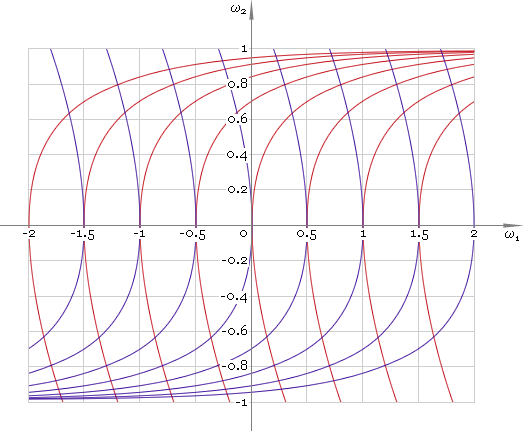 Fig. 1. Phase plane.
As one can see to solve the problem it is necessary to apply maximum negative driving torque and then switch it to maximum positive. Now the only point we should make clear is time instance tsw of switching driving moment from −Umax to Umax. To find time instance tsw let us write down solution of equation (1) for U that does not depend on time:
| (9) |
where C0 and C1 are arbitrary constants. The angular velocity respectively is
| (10) |
Accepting boundary conditions (3) we find time instance tsw:
 |
(11) |
Now knowing switch instance tsw we can build solution of the problem in phase plane — fig. 2. Here switching process is highlighted in green.
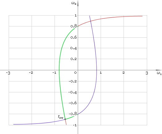 Fig. 2. Velocity switching.
Dependence of angular displacement, velocity and acceleration on time is depicted in figures 3–5 respectively.
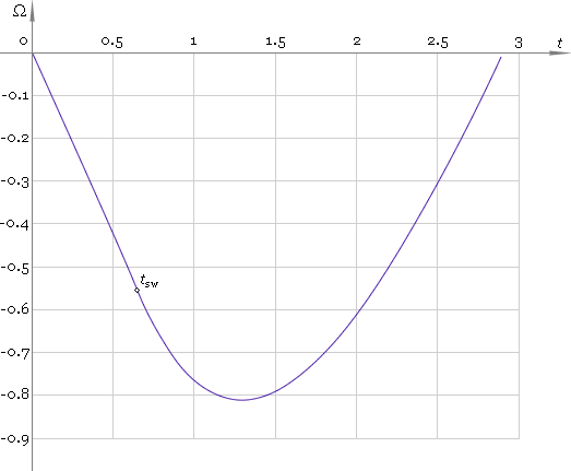 Fig. 3. Angular displacement.
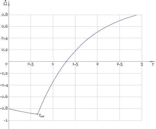 Fig. 4. Angular velocity.
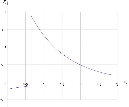 Fig. 5. Angular acceleration.
|
|
|||||||||||||
|
|||||||||||||


